We have cross correlated the information between defects for the
layer 2 module from a
test beam analysis by Selenia Dittongo and calibration data
taken in the lab at UCSB in April and July and in August at CERN.
Note that the bad-channel-list was generated from calibration runs performed
in April. The test-for-shorts had not yet been developed, so shorts were
not explicitely flagged in the list. The results of the comparison
are summarized here:
Pinholes
Pinhole channels are always dead (charge injection, LED scans, particles).
Channels next to a pinhole (CNPs) are sometimes dead, and sometimes not.
For example, all CNPs on the p-side were dead under charge injection in
the tests performed in April. They were all OK in the tests performed
in July and August. Conversely, all CNPs on the n side
were OK in April and July but dead
in August. We do not understand what causes this. Note also that on one
side of the layer 5 module, two channels next to a pinhole are dead
instead of one (or zero).
Results on CNPs from charge injection, LED scans and MIPs are in
agreement, with the exception of a handful of channels on the
p side. These are reported as not seeing the beam but they are
OK under charge injection at the testbeam. (Channels 3-98, 6-32, 6-34,
6-59, 6-61). These should probably be rechecked.
By plucking the pinhole, previously dead CNPs come back to life.
If a CNP is dead, it is also dead under charge injection after it is
plucked. This suggests that CNPs are killed by something that happens inside
the chip, not inside the detector.
There were two pinholes flagged by DFA testing which
ended up being OK in charge injection and in the beam
test (p side, channels 2-126 and 3-9). We went back and looked
at the DFA test data. The current draws were very large but not as large
as for all other pinholes. The flagging of these channels as pinholes
was probably not correct.
Inconsistencies between Selenia's analysis and the list of
bad channels from calibration
Noisy channels flagged by Selenia. These are due to two effects:
Readout shorts
that were not flagged in the original bad channel list but which were
detected by the new test-for-shorts performed at the testbeam.
Channels with higher than average offsets, typically of order 2 sigmas
from the mean offset which was used to set the threshold on the chip.
Channels which are OK in Selenia's analysis but are flagged as bad
in the bad-channel-list.
Some of these were inefficient under charge injection in April,
but actually OK under identical conditions at the testbeam. The reason
for this is not understood.
There are a few pairs of channel which behaved as shorts in April, but
OK at the testbeam. The reason for this is not understood.
Channels which are dead in Selenia's analysis but are flagged as OK
in the bad-channel-list.
The measured noise for some of these channels is consistent
with the channels being unbonded.
The remaining channels are flagged as shorts in the test-for-shorts.
In conclusion, calibration data and beam data are in good agreement.
The bad-channel-list to be used in the test beam analysis should be updated.
We do not understand the behavior of the electronics for
CNPs. This is mostly an
academic question because (1) the rad hard design is different and, (2)
the plan in production is to pluck the channels with pinholes.
We also do not understand why a small number of shorts magically fixed
themselves between April and August.
We have extracted histograms of avearage TOT vs CAL_DAC for each channel,
different shaping times,
and for all
thresholds used at test beam.
HBOOK files containing these
histograms are available in a
gzipped tarfile. The file names are ttq_lx_y_z.rz,
where
x is the layer number (2 or 5)
y is 10 * the nominal threshold in fC
z is the shaping time (100 or 200)
NOTE: Due to a mistake in downloading the calibration constants,
the data for the layer 5 p side at 200 nsec shaping time for
a nominal threshold of 1.0 fC
should be discarded.
The HBOOK histograms IDs are 900000 + 128 * chip_number + channel_number
and the numbering convention is described
above.
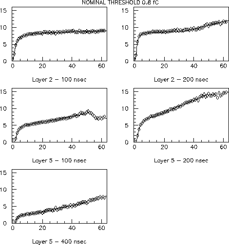
Sample histograms
are shown below (The CAL_DAC value is plotted
on the x-axis, the average TOT value is plotted on the
y-axis.
The histograms have been
obtained from charge injection runs at fixed values of thresholds
and have been individually fit
to an empirical functional form.
Noise hits have been rejected using the
time stamp information.
Even in the absence of noise
one expects some scatter in the TOT value for a given charge on
a given channel. This is because even though the timing of the
charge injection pulse is correlated
with the system clock, the output of the shaper is sampled with a
frequency lower than that of the system clock. Because of this scatter,
it is necessary to collect several TOT samples in order to calculate
the mean average TOT response as a function of charge.
Note that the TOT vs CAL_DAC shapes for the layer 2 and the layer 5 modules are
different. The layer 2 module uses version 1 of the rad soft chip,
while the layer 5 module uses version 2. There have been some
changes in the shaper design between the two versions of the chip.
The drop-off in average TOT for the layer 5 module at very high values
of injected charge for the 100 nsec shaping time had also been seen
by Al Eisner on the bench.
Note also that at 200 nsec shaping time the layer 5 response saturates
the TOT dynamic range at high values of charge (recall that at the
testbeam we operated the modules at 200 nsec with "no skip" in
order to study the improvement in position resolution which could in
principle be obtained with better TOT time resolution).
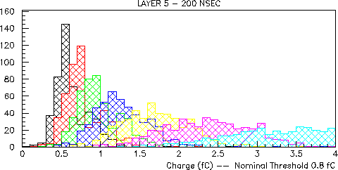
For a given nominal threshold, we expect channel-to-channel variations
in the TOT response to charge injection due to
Differences in the charge injection capacitors
Differences in the gains
Differences in the offsets
Differences in the responses of the shaping circuits
It is easier to look at these differences
using the TOT to CAL_DAC lookup
tables, rather than the parameters from the functional fits, since these
parameters tend to be highly correlated. The following figure shows the
charge response as a function of TOT for the layer 5 module at 200
nsec shaping time for different channels at a nominal threshold of 0.8 fC.
The charge has been obtained from the CAL_DAC value using nominal
values for the
charge injecting capacitor (65 fC) and the CAL_DAC to voltage conversion
(1 count = 8.217 mV). For each value of TOT between 1 and 7, we
loop over all channels and, using the lookup tables, we accumulate the
corresponding charge into a histogram. We then show all seven histograms
together (in different colors):
The fact that the histograms are not well separated means that using
a channel independent lookup table as a function of shaping time and
nominal threshold would result in a significant
degradation of the intrinsic analog resolution.
The effect on the
position resolution is not clear without further study.
One of the most important reasons for the spread in response is
probably due to the large spread in offsets.
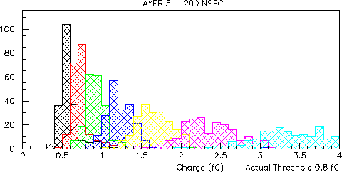
Using the measured offsets
it is possible to look at the spred in TOT response for channels
with constant actual threshold (i.e. constant threshold-offset).
This is shown in the Figure below, where we select channels with
actual threshold within 0.5 threshold DAC counts of 0.8 fC
(1 count = 4.29 mV. At 200 nsec shaping time the gain is
approximately 83 mV/fC, therefore 0.5 counts correspond to 0.025 fC).
The separation between histograms has improved considerably. This
suggests that we should also try to generate lookup tables which
are just functions of the actual threshold and the shaping time.
Preliminary lookup tables based on (threshold-offset) have been
generated and are available in a
gzipped tarfile. These lookup tables have been generated
(for the different chip versions and different shaping times)
by combining all of the calibration data, and by taking the
two-sigma-truncated mean
response of all channels as a function of threshold-offset.
Since no smoothing or fitting was done, the lookup tables are still
a little ragged near the near the edges where the statistics are poor.
Unfortunately the discussion above is not entirely consistent.
The plot for Actual Threshold 0.8 fC indicates that
TOT=1 corresponds on average to something like 0.5 fC. This is
significantly lower than the 0.8 fC threshold. This could be due to
a shift in offset (remember, Actual Threshold = (threshold-offset)),
or to something else. Note that the gain/offset and TOT calibration data were
taken on different days.
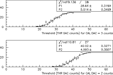
In order to try to understand what is going on, we can look in detail at
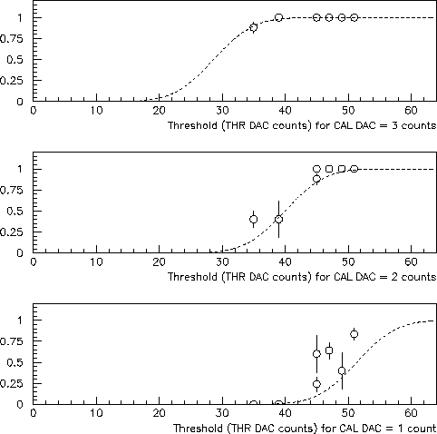
the calibration data for one channel on the Layer 5 module, p-side,
shaping time = 200 nsec. The gain/offset calibration was based on two
threshold scans at fixed charge injection with CAL DAC values of 2 and 3
(corresponding to approximately 1 and 1.5 fC). The error function fits
are shown below.
Unfortunately this was done only once, so we cannot directly compare
these curves with curves taken at a different time. However,
by taking data from different TOT calibration runs we can obtain a
(small) set of points that can be directly compared with those above.
This is shown in the next figure.
These three plots show the hit fractions for the same channel from the
TOT calibration runs compared to expectations based on the parametrizations
obtained from the threshold scans used in the gain/offset calibration
(these are the dashed curves).
The comparison is made for CAL DAC = 1,2, and 3.
We actually did not directly measure the parametrization for CAL DAC = 1.
What is shown in the third plot is the expected parametrization
for CAL DAC = 1 based on the CAL DAC = 2 and 3 parametrizations and
assuming linearity in the response.
Note that not only were the dashed
parametrizations obtained on a different day than the day on which
the points were taken, but also not all points were taken on the
same day.
A shift in offsets would effectively result in a shift (to the
left or to the right) of the dashed line predictions.
The CAL DAC = 2 and 3 points agree fairly well with the parametrization,
but since most of them are so close to 100% they would also
be consistent with a parametrization that is significantly shifted
to the left (for example).
On the other hand, the CAL DAC = 1 points are in poor agreement
with the parametrization. Better agreement could be obtained
by shifting the parametrization to the left.
The higher than expected fraction of hits at CAL DAC = 1 is directly
responsible for the lower than expected threshold inferred from the
TOT response curves.
One may worry that the CAL DAC = 1 response could be seriously
biased by noise hits. However, the time stamp information shows
that the hits are correlated with charge injection.
It is possible that at very low values of charge injection (i.e.
CAL DAC = 1) the system does not respond as expected. It turns out
that this was never checked at the UCSB
Test Bench.
We will check this soon.
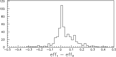
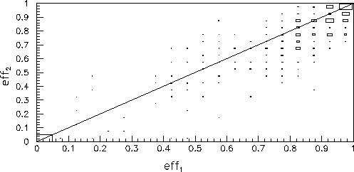
We have also looked for higher statistics evidence for or
against the hypothesis of an offset shift. This is done in
the following way on a channel-by-channel basis:
We use the TOT calibration data at a nominal
threshold of 1.4 fC to calculate the hit efficiency (eff1)
for CAL DAC = 2.
We extract from the gain/offset calibrations the hit efficiency
at the same threshold for the same value of CAL DAC
(eff2).
We then plot eff1 - eff2 and
eff2 vs. eff1,
see below.
There is a systematic difference between eff1 and
eff2. The sign of this difference is consistent with
an offset shift of the same sign as the shift needed to explain
the TOT = 1 inconsistency.